Bent and Motorized
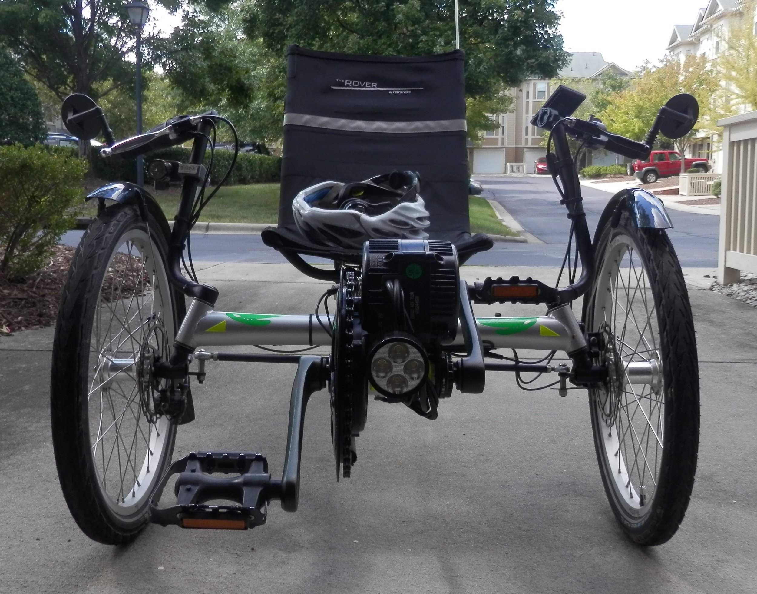
This is the story of my Rover and how it became motorized. The Rover is a 3-wheeled recumbent, aka "bent", bicycle manufactured by Terratrike in Grand Rapids, MI. Terratrike makes 6 different models of recumbent bicycles, of which the Rover is the low end model. The Rover is a sturdy, reliable bike; a testament to Terratrike's excellent design and quality. I purchased the bike in May of 2013, used, through Craigslist. There were no bike shops in my area selling recumbent bicycles at that time. Most bike dealers don't carry recumbent bikes because they take up too much floor space. To which I say, "Stand 'em up against the wall or hang 'em from the ceiling."
I bought the bike shortly after I sold my Prius. I made a conscious decision at that time to live with only one car and to ride the bike to work as much as possible. At the time I worked for IBM and lived only 4.5 miles from work. A contributing factor to this decision is that the area where I live and work is loaded with jogging and bike paths. The 1st mile of my commute is on a road with moderate traffic and the rest is on the bike paths. The Rover is not a low slung, racy looking bike but it's solid. It's reliability is largely due to the simple frame and 8-speed Sturmey Archer hub. This is the same style hub as found on most 3-speed bicycles, designed and refined by a company over 100 years old! I rode a bike with a Sturmey Archer hub when I was a kid, before 8-tracks were invented. You could probably shoot a bullet in that hub and it would continue to work. My only complaint about the Rover is the Zoom disc brakes on the front wheels. They are hard to keep adjusted and they slip if not adjusted properly.
About the frame: It's all welded, tubular construction with one square tube down the center, extending from the front crank hub all the way back to the rear wheel assembly. There are basically four parts to the whole bike, the front tube with crank hub, the middle tube with front wheels and steering assembly, the back tube with seat and rear wheel mount and the seat. It's very easy to take apart, with only 4 hex bolts to loosen to slide the three square tube assemblies apart. Not much to go wrong.
I rode the bike back and forth to work for about 2 years with no motor (no breakdowns, one flat!). Just before Christmas of 2014 I started ordering the parts to motorize the bike. The longest lead time, by far, was the 50V battery since it came by slow boat from China (ordered Feb 2015, received in May). I did not finish the assembly until May of 2015. What follows is an account of the parts selection and final assembly of the pedal assist motor assembly.
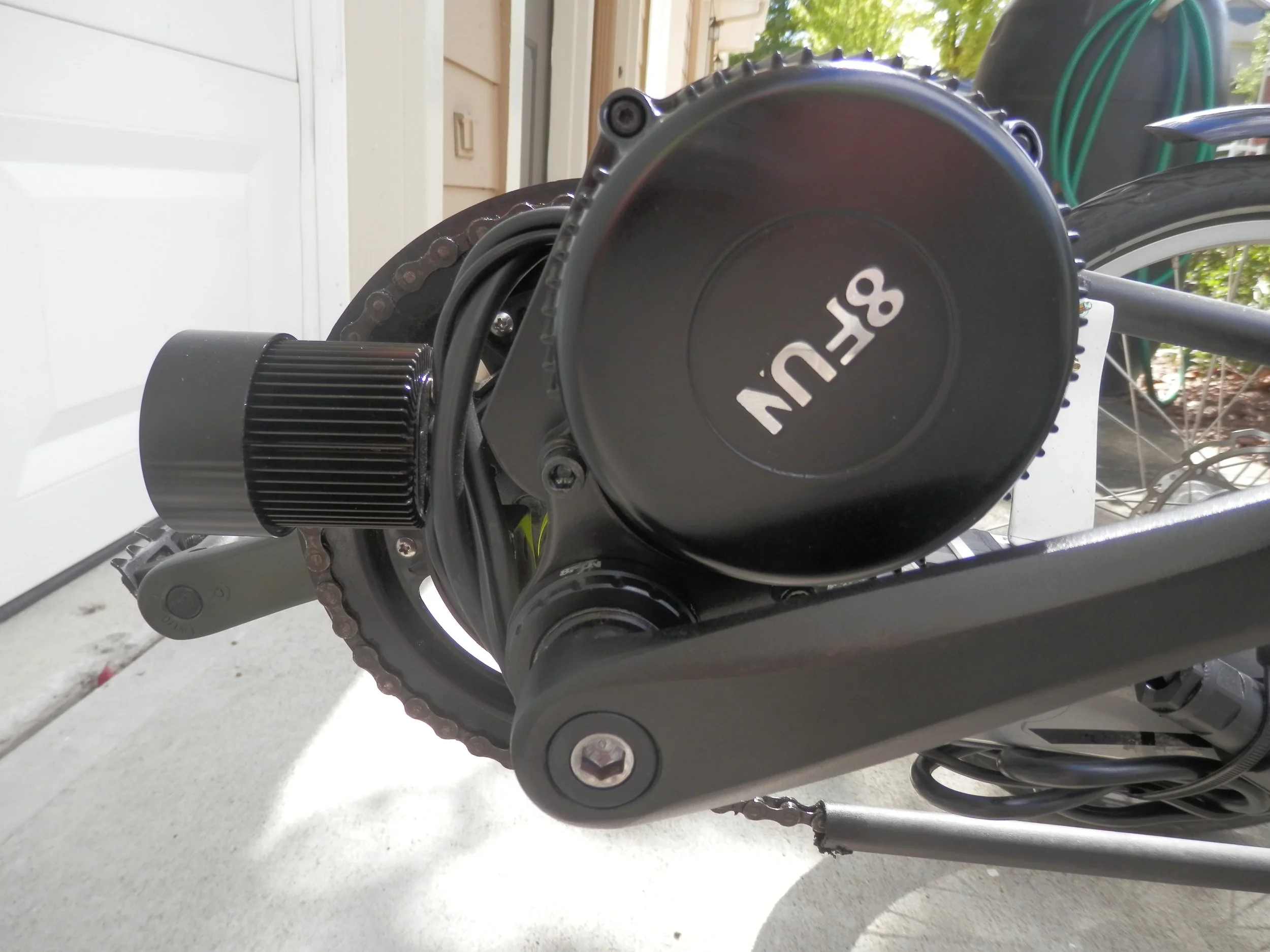
I did some research on the web for diy motor kits and finally decided on the BBS02, 8Fun crank kit from Bafang. I picked the crank hub motor as opposed to a wheel hub motor so I could keep the aforementioned 8-speed hub. I purchased the kit from EM3ev, sans battery. I debated whether to save money on the 36V kit or go with the more powerful 48V kit. I settled on the 48V kit and felt it well worth the extra $100 motor cost plus extra battery cost. The kit comes with everything you need to replace the bike crank assembly with the sealed crank plus motor, BBS02 assembly. The motor assembly uses a standard 33.5mm dia crank spindle, also sealed, so no need to mess with bearings. Mounted to the crank assembly is a 44T chainwheel which is larger than the one that comes with the Rover. The larger chainwheel makes traveling at 25mph in 8th gear a breeze (pun intended). Note the motor must be mounted to rest against the top of the frame because that's the direction of torque. The kit also comes with brake handles with sensor wiring to signal the motor control to cut off when the brakes are applied. I wanted to keep one of the Rover standard brake handles, with its built in brake lock, so I purchased an additional ebrake sensor.
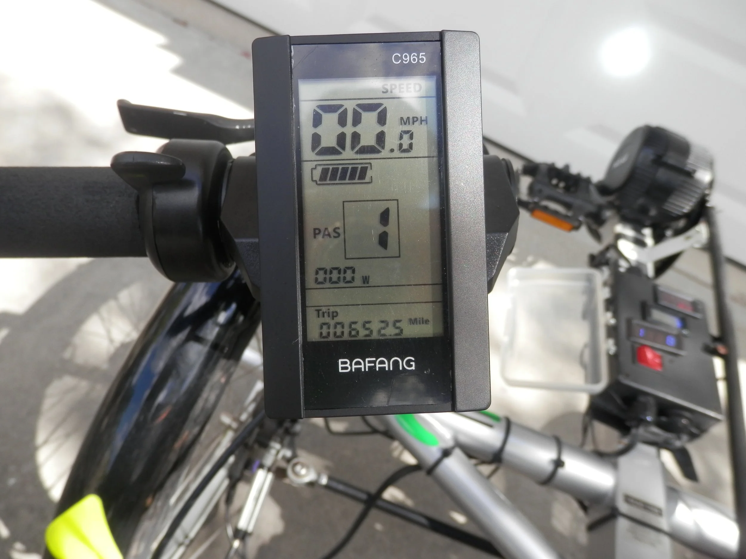
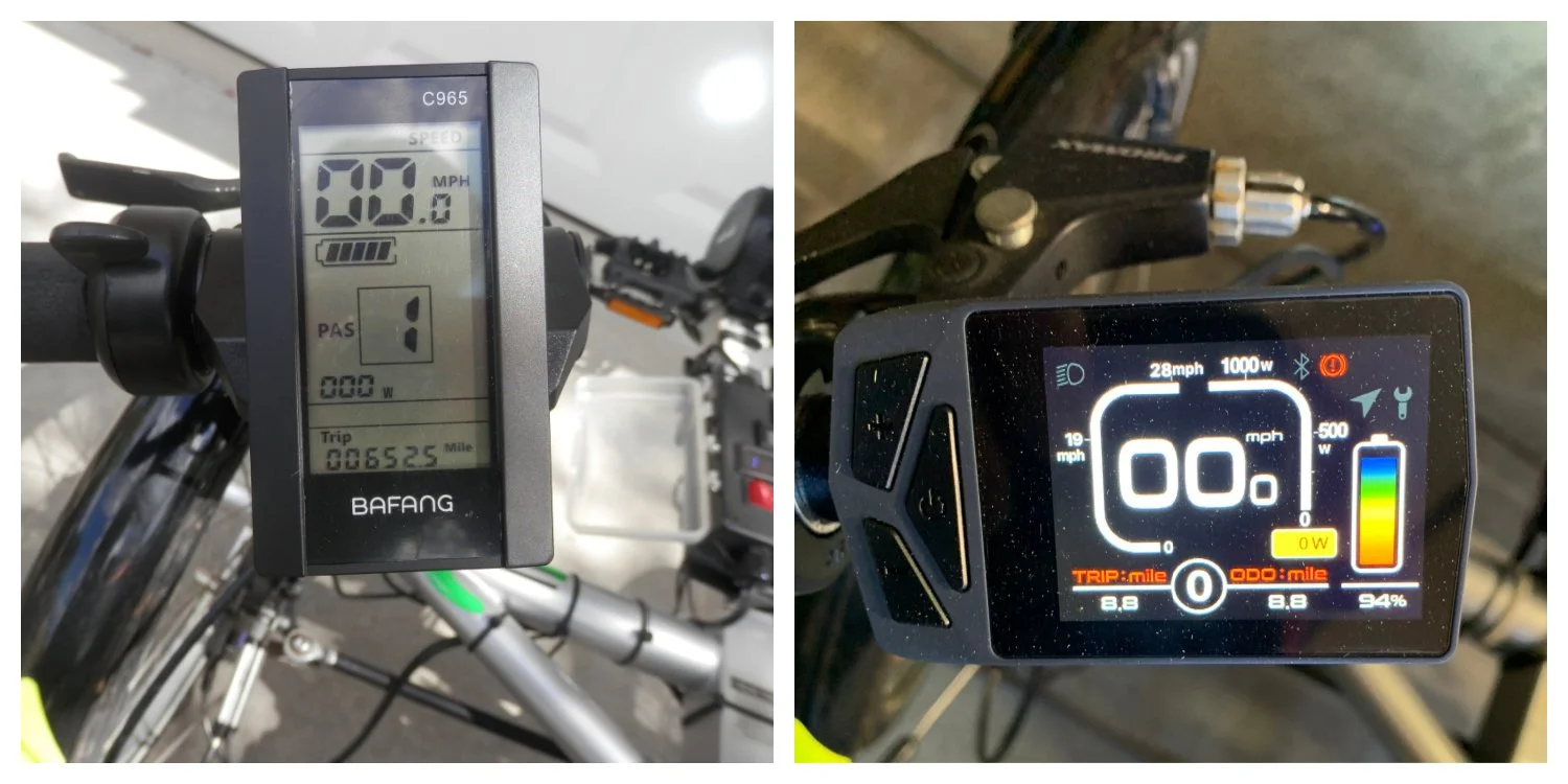
The kit has some options for the motor control panel and software. I chose the C965 controller with 3 PAS (pedal assist) settings. I think you can get a controller with 5 or 8 settings but I've found 3 to be enough. The PAS setting regulates max power to the motor with 1 being lowest power, least assist, and 3 being max power, max assist. I can easily pedal 25 mph at PAS 3 which is the fastest I want to go on this bike (no stopping or turning quickly at that speed!). The controller software can be easily configured for wheel size (for the speed sensor), miles / kilometers and max speed. I like the max speed, which I set for 40.2 km/hr = 25mph, Power to the motor automatically shuts off when the speed reaches 25mph. There is no built in clock, but there are several indicators for travel time and distance as well as an odometer. Note the custom dashboard mounted on the center bar in the background. Another fun project for a future blog post.
I spent some time choosing the battery. EM3ev has some recommended 48V battery packs on their site which are no doubt high quality (they tout using Samsung cells for reliability). The motor is rated 750W at 48V, 15.6A. My route to work was about 30 min each way so I looked for a 48V, 750Wh, 15+Ah battery, figuring extra capacity since I wouldn't be consuming max power except on hills. EM3ev offers an 8P pack with 15.2Ah capacity for $665. I started looking around the web and found a big price range for battery packs with this capacity from under $200 to over $800. For better or worse (after 4 months usage I'm still very satisfied) I decided to go with a 13 cell, 48V, 15ah pack, direct from China for $338. I ordered the battery through ebay from Vpower. They actually had a web site and seemed to be in the electric bike business so I decided to take a chance. The battery kit came with charger and a bag that was supposed to make it easier to mount the battery. The bag was worthless but I have no complaints about the battery pack and charger. One important feature to look for if you start hunting for a battery pack is the BPS, Battery Protection Circuit. Unless you are a lithium battery expert and a whiz with voltage sense/current sense circuit design, I strongly recommend you only go with a fully assembled pack with matching BPS. A lithium cell will overheat and catch fire if shorted or overcharged. As stated earlier, it took almost 4 months to receive the pack. You can speed that up by paying an extra $150 for shipping if you want.
I ordered a few extra parts for the assembly, a 15A inline, water proof connector to make it easy to disconnect the motor from the battery, and a package of 20 11" cable ties. I ordered the inline connector assembly, 4pin 15A IP68 Waterproof Electric Screw Connector Plug Socket, from a supplier on eBay.
Assembly:
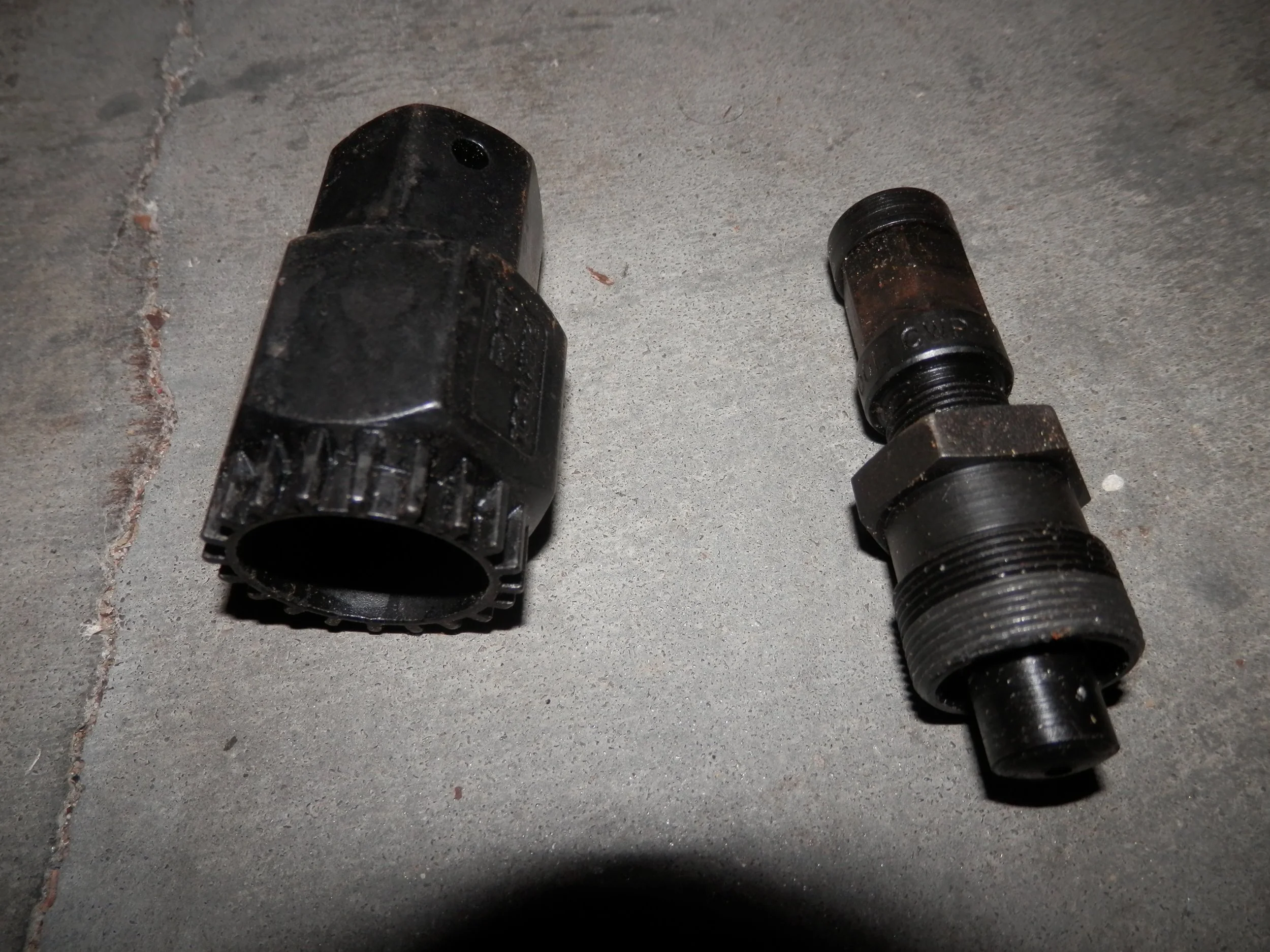
I received the BBS02 kit first so I did a test run to assemble it on the peddle crank to verify no surprises. I needed to purchase two tools to remove the old crank assembly, a crank puller and a spindle nut remover (for want of a better name). Note the bumps around the circumference of the spindle nut remover which match up with notches on the nut itself. Best to remove the crank, take a picture of the spindle nut and show that to your bike repair shop to get the right tool.
There are some good youtube videos out there that show how to remove and replace a crank hub including this video that shows how to install the Bafang motor on a standard bike hub. The installation went without a hitch, esp. since there were no bearings to deal with. I removed the Bafang motor and re-installed the original Rover crank and sprocket assembly, no problem.
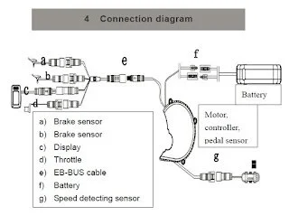
As soon as I received the battery the real installation began. The motor has a cable for power and control that connects to a breakout cable harness to six connections, power, left and right brake sensor, throttle, speed sensor and controller.
The connectors are color coded to make it easier to match up to the respective cables. The following cable connection diagram comes from the BBS01 installation manual.
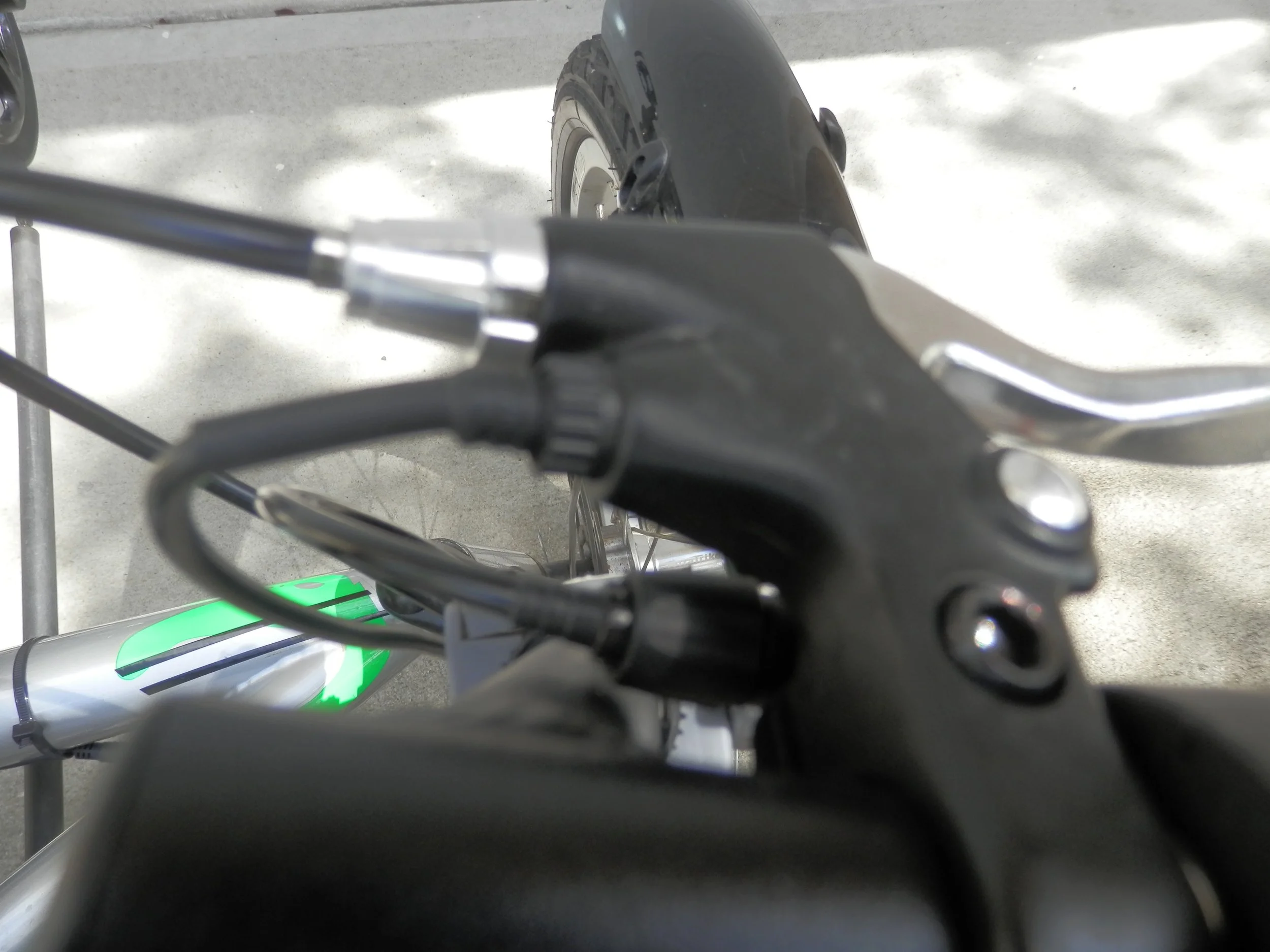
I replaced the Rover's right brake handle with the brake handle with built in brake sensor that came with the motor kit. The sensor signals the motor controller to shut down the motor when the brake is engaged. You can see the extra sensor wire connected to the brake handle in this pic.
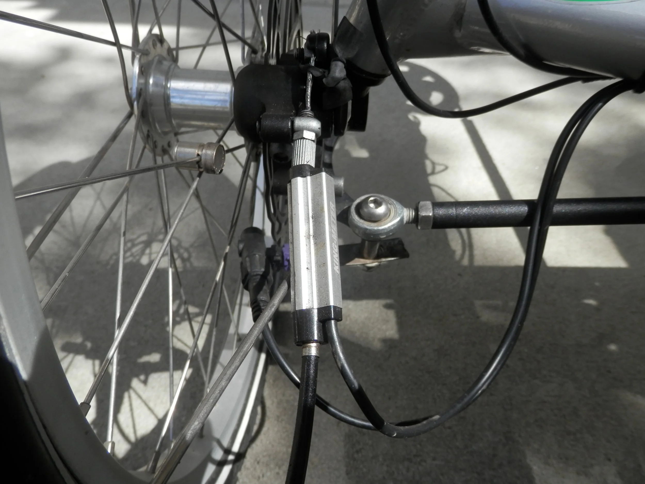
I wanted to keep the Rover's left brake handle with built in brake lock, so I had to add the inline esensor between the brake cable and the brake caliper. This part did not come with the kit and had to be ordered separately.
I mounted the motor controller display and manual throttle on the left hand grip since the hub speed controller was already mounted on the right grip. The throttle and control panel were a tight fit and I had to cut away some of the foam hand grip to get them to fit on the bar. The manual throttle controller is mounted just to the left of the C965 display in this pic. You can also see the speed, battery level, PAS setting and odometer reading on the display. NOTE: I’ve recently upgraded the controller to a Varstom EKD01 color display with Bluetooth. I love it. It syncs with the GPS on my phone to provide turn by turn directions on the display.
I mounted the speed sensor on an L bracket attached to the steering bar bolt on the left wheel.
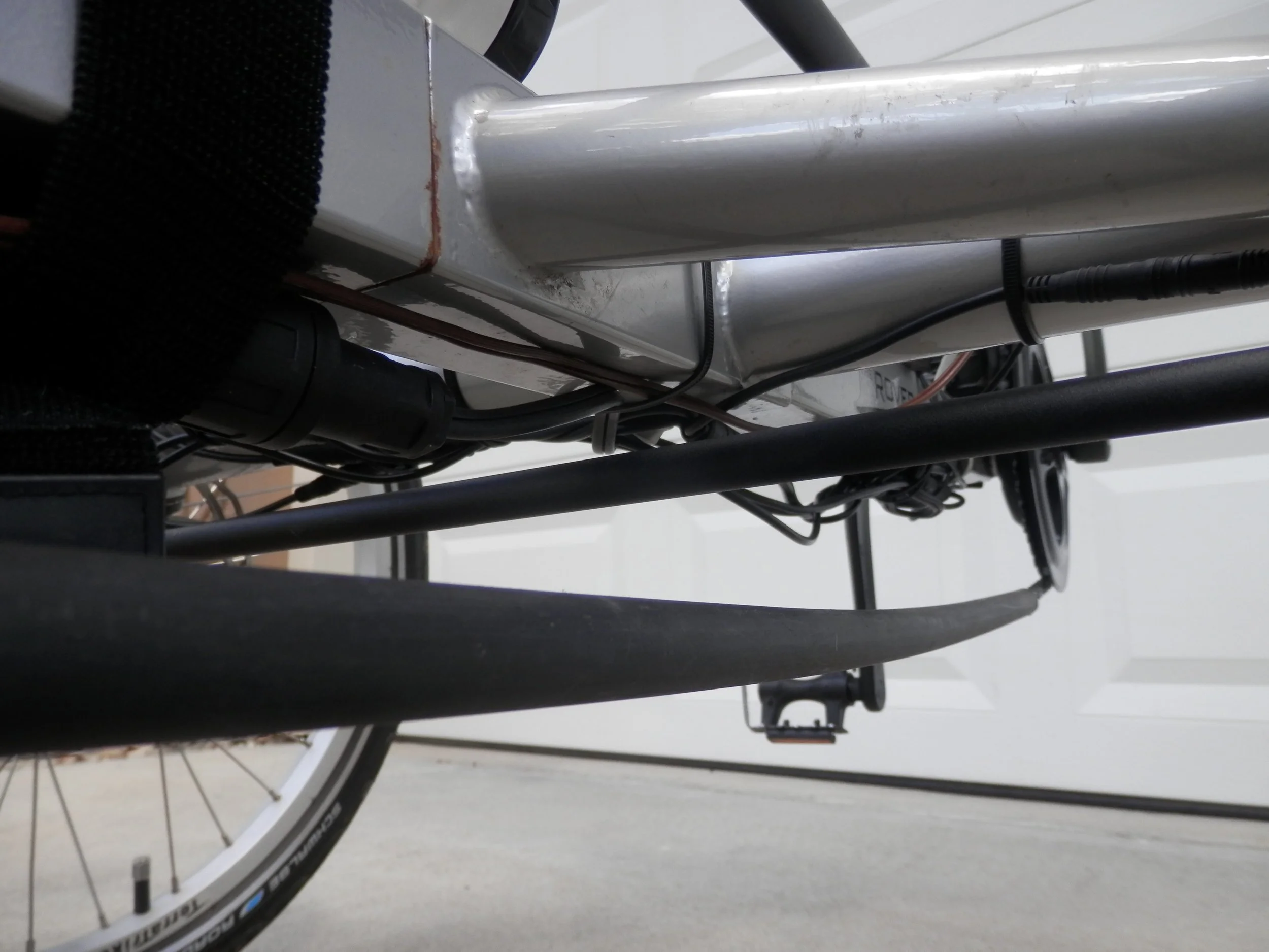
All of the cables were connected to the cable harness and run under the frame with cable ties and enough slack to accommodate full steering in either direction.
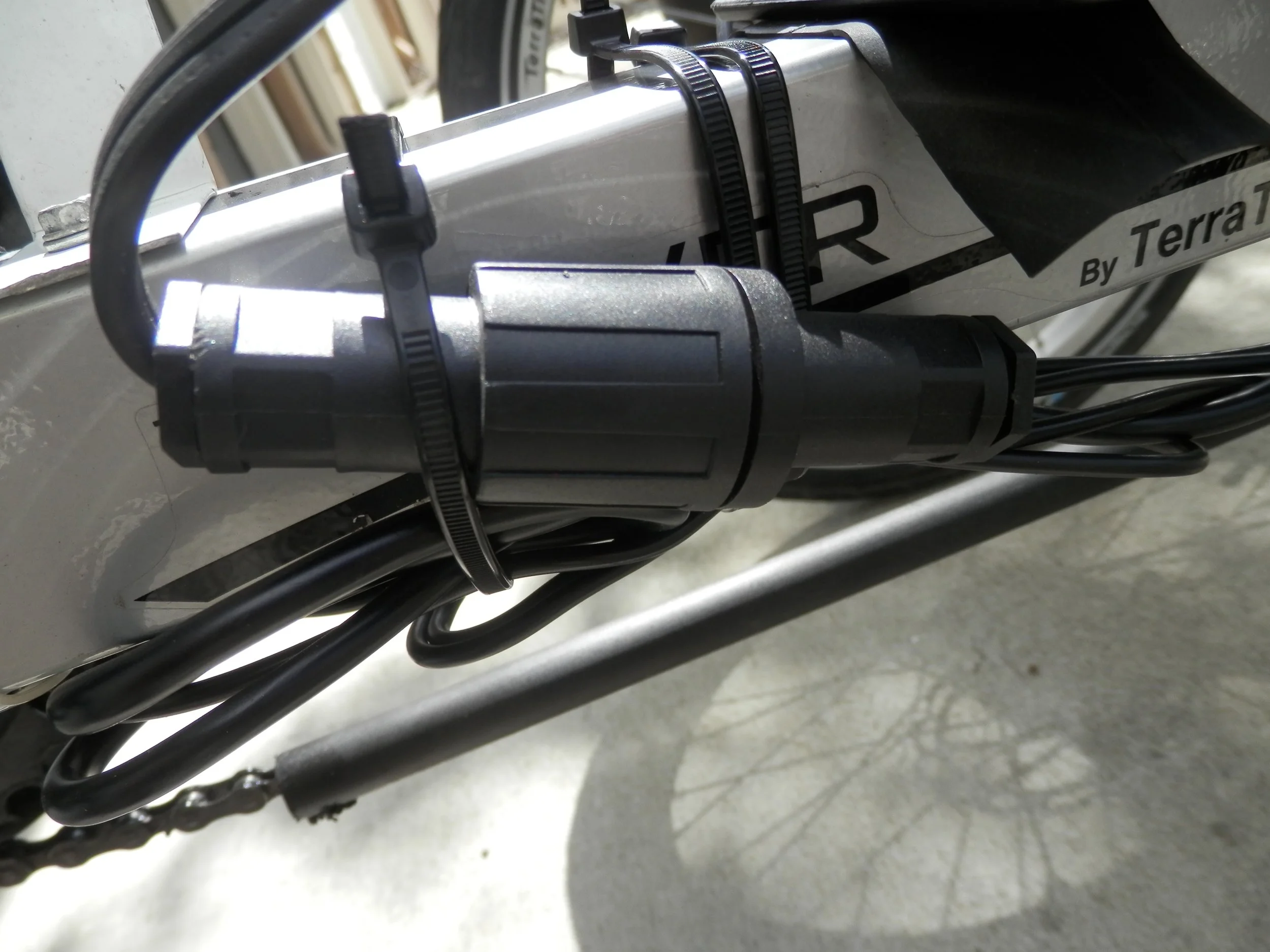
The battery pack uses a standard, male AC appliance plug for the 48V DC output. Only two of the three prongs are used, center and one prong on the left or right (use a voltmeter to verify which). I used an AC appliance cord, the kind you use to plug in a computer monitor or TV, to connect the battery power to the motor. I cut off the plug end of the cord (the end that normally plugs in the wall) and attached the wires to one plug of the inline, waterproof connector. I attached the other plug of the connector to the 48V input power line to the motor.
The Battery Mount:
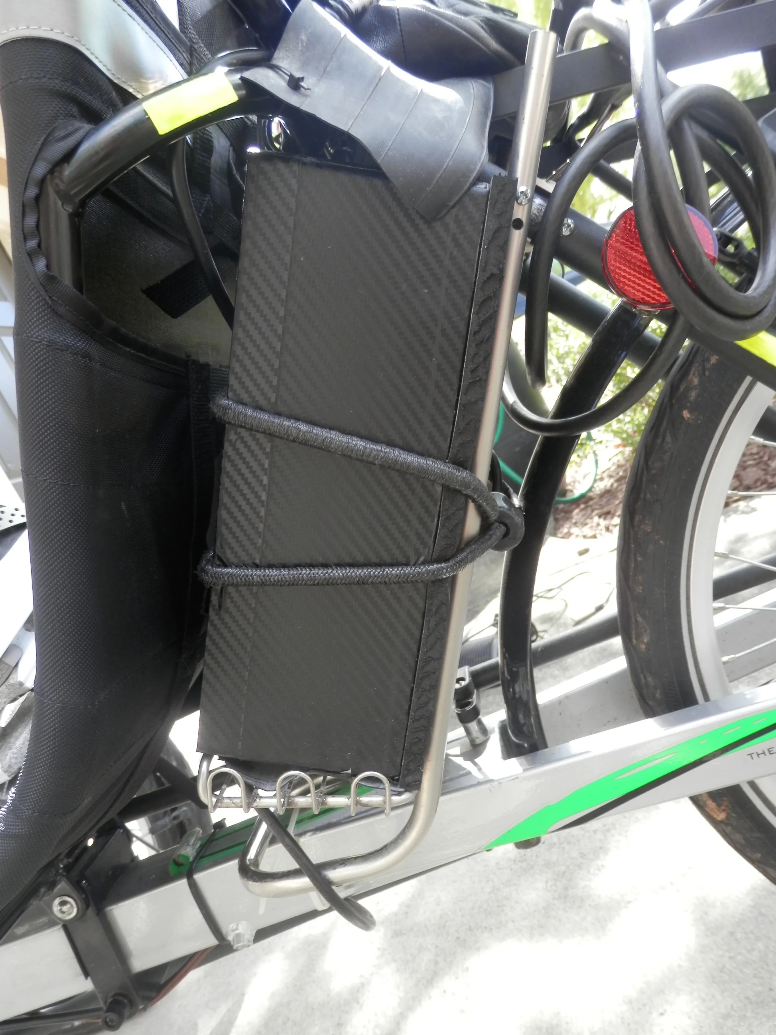
I decided to mount the battery behind the seat. It would have been easier to mount it on the rack over the rear wheel but I wanted to leave that open to carry my backpack to work. I used a custom battery mount which I made from a shower caddy. Hey it worked and it looked pretty good after modifying it to fit between the seat and the rear wheel. I used a caddy very much like the picture above. I broke off all but the bottom wire shelf, bent the bottom tube base so that the frame would sit at an angle and sawed off the vertical tubes to the right length to fit between the bike frame and the rack attached to the seat back. It ended up being a really tight fit and as you can see I used a precision made bungee cord to hold the battery pack against the custom frame. Note the carefully designed rubber flap to protect the top of the pack, where the battery switch, input and output plugs reside, from rain.
The top end of the battery pack has the 48VDC output plug, power switch and the input power connector for the charger. Note the manufacturer used a standard 3-pin DIN connector for the battery charger hookup.
Here is a picture of the chunky, 327W charger. Note the vent holes for the internal fan.
At this point I was ready (with a little trepidation) to power up the motor controller and motor. I switched on the battery and nothing happened. Actually that was good because that meant the control circuit was working. The button controller that I mounted on the left down tube controls power to the motor. I pressed the center button for about 2 sec and was rewarded with the C965 control panel lighting up. Still the motor did not engage. Good, since it shouldn't do anything unless I either crank the pedal or engage the manual throttle. I pushed on the manual throttle and immediately the bike jerked forward. Yeah!
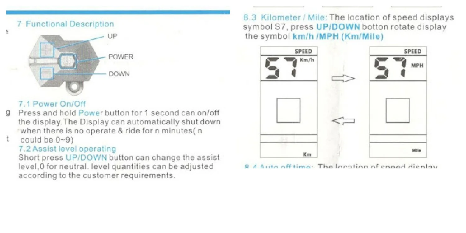
Next step was to fix some settings in the control software for the wheel size (for accurate mph calculation) and the max speed (the speed at which power is cut-off to the motor). It's important for the speed sensor to be mounted properly next to the wheel, since the controller will not work right and will even flash an error if it does not detect the wheel rotation. The C965 manual, available from the EM3ev site, shows how to configure the software by pressing the right combination of buttons on the 3-button controller. I've snipped a couple sections of the manual to give an idea how it works.
Once I finished the setup, everything worked perfectly. I was worried the motor response might be a little jerky when applying rotation on the pedals, but it engages and disengages very smoothly at all PAS levels. The pedal assist does just what it says, it gives you a little (or a lot of) boost while you pedal and only while you pedal. I can make the motor drive the chain without pedaling by pushing on the manual throttle control. All this makes going up hills a piece of cake. I can also pedal the bike with no motor assist (controller off) and there is no noticeable drag from the motor, since the sprocket fully disengages from the motor drive when not in use.
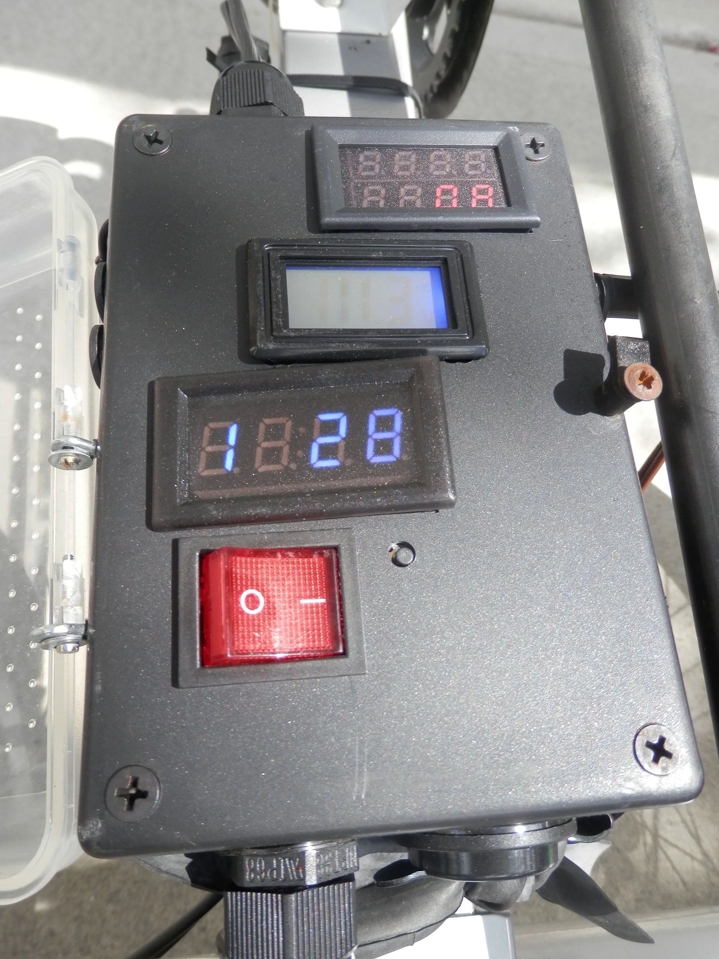
This is a picture of my custom dashboard. The idea for it started when I realized that the C965 control panel did not have a built in clock or a temperature sensor. Then the idea grew, as most do, to include a Volt/Amp meter, an on/off switch, a USB charger port and 4 auxiliary power ports. I bought all the parts through eBay and of course most of them came from China. It's amazing how cheap some of this stuff is if you're willing to wait 6 weeks to get it and are willing to take a risk on quality. I'm not going to go into the details of how I made this except to list some of the major parts. The dashboard was designed to be inserted into the 48VDC supply line between the battery and the motor.
A case to mount on the center tube. It's hard to see in this pic but the case has two fins sticking out of the base that made it easy to screw into the frame.
DC-DC 15-50V to 12V 3A step down transformer.
A 200V/100A LED Volt/Ammeter (12V display power)
12V digital time display
12V digital F or C temperature sense/display
Auto 12V to 5V 1A dual USB port
DC power jacks and plugs (same type used on old AC/DC adapters), 4 sets.
Cable strain relief with gasket (2).
Hobby board, cut to size
18 awg black and red wire
Inline mini fuse holders for 50V 20A and 12V 5A circuits.
Fly fishing box with clear plastic cover.
That last item was found while I was searching for anything cheap that had a clear cover on it to fit the top of the dashboard (to protect against rain). The cover on the fly fishing box was a perfect fit.
The 12VDC circuit for the auxiliary devices worked out real well. I bought a motorcycle small LED headlight and blinking red tail light for the front and rear of the bike. I'll probably add a string of flashing lights to go up the flag pole.
Total cost incl motor kit, battery and dashboard parts, about $950. Very close to what I paid for the Rover. So, except for you graphite racing bike aficionados, shelling out $2000 for a bike may seem a bit pricey but when you consider what I've saved in insurance, gas and maintenance costs by not having a 2nd car, it's a steal.
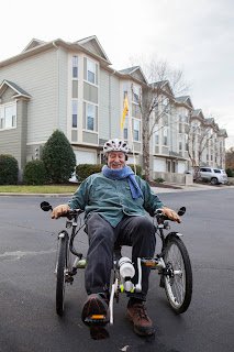
I'll close here with a couple more pics of the trike. The weight of the Rover started at about 42 lbs. I figure I've added another 30lbs with the accessories for a total weight of about 75lbs. Yeah, you're not going to carry this trike around under one arm. The motorized Rover is a blast to ride and I've been really pleased with the power and reliability of the Bafang motor and vPower battery pack. Honk (lightly) if you see me cruising down the road. UPDATE: Since the writing of this article in 2015 (the bike is still running fine btw), my job relocated farther from home (Lenovo bought the x86 server business from IBM) so that my round trip turned into 15 miles. I continued to ride the trike every day to work, rain or shine for another year. It was about a 30 minute ride to work, about the same as most people’s commute on crowded freeways. I’ve since retired from Lenovo but still ride the bike for fun, with the grandkids and in the yearly neighborhood 4th of July parade. Now I get to focus on converting more eBikes. More fun!

